Nand gate circuit diagram circuits inputs input through pull down electronic explanation button connected then power Gate nand circuit circuitlab description Nand gate circuit diagram and working explanation
digital logic - Building a 3-input NAND or NOR gate with 2-input NAND
Nand gate
Gate nand nor xnor circuit vhdl xor logic simulate verify circuits wiring engineersgarage
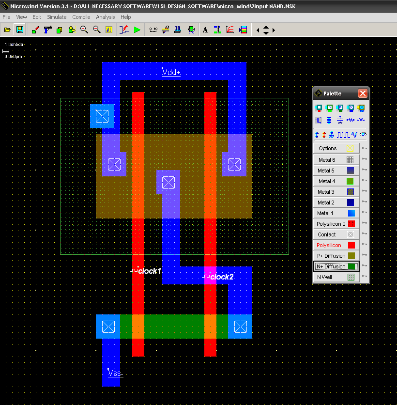
Gate nand logic input output gates nor universal hyperphysics will second each combinationsNand theorem gate demorgan example circuits operations electronics digital Digital logicNand cmos gate input layout microwind pspice.
Digital logic nand gate – universal gateDigital logic nand gate(universal gate),its symbols & schematics Vhdl tutorial – 5: design, simulate and verify nand, nor, xor and xnorNand schematic decoder.

Nand gate nmos logic transistor schematic using digital universal ic symbols its two given below
Nand gate schematic diagramNand logic clipart symbol tally gatter boolean logische table explain learnlearn verbinden quia unrealengine acsl clipartkey Nand gateNand gate circuit diagram and working explanation.
Nand gateNand implementation ic block precautions Digital logicExplain why the nand gate is known as a universal gate..

Nand gate schematic diagram
Nand nor gate transistor logic cmos why input circuit gates nmos size diagram preferred over level logical output industry capacitanceCmos 2 input nand gate Gate nand universal logic nor function digital into made electrical other basic which given below figureGate nand circuit diagram gates flop flip sr logic using table truth resistor explanation circuits connected digital button working.
.